Over the years we have refined and fine-tuned our sensitivity to better understand the needs of our clients. Our design work reflects your needs, esthetics and personal preferences as well as those of your client.
Working drawings are the third and last phase of the overall Construction Project (Art. 23, D. L. 18 Aprile 2016 n. 50).
Working drawings provide dimensioned, graphical information that can be used by a contractor to construct the works, or by suppliers to fabricate components of the works or to assemble or install components. They may include architectural drawings, structural drawings, civil drawings, mechanical drawings, electrical drawings, and so on.
In broad terms, the working drawings are the most technically advanced phase of the overall project.
Specifically, the working drawings develop and engineer every segment of the project, focusing on technical details while following mandatory rules and regulations.
The documents, according to the Italian normative reference (art. 34-43, L. n. 201/2010), are the following:
- Art. 34- Generale report
- Art. 35- Specialist report
- Art. 36- Working drawings
- Art. 37- Structure and plants calculations
- Art. 38- Maintenance plan
- Art. 39- Security plan
- Art. 40- Work schedule
- Art. 41- Unit prices list
- Art. 42- Bill of quantity
- Art. 43- Contract scheme and tender specifications
According to art. 36, the working drawings:
a) Develop all the drawings of the final design in the allowed or prescribed scales;
b) Drawings necessary for the execution of the works;
c) Contain all the details of construction and the manner of execution of details, informed by the results, studies and investigations carried out during the final design;
d) Include drawings illustrating how to execute the details;
e) Conform to the requirements laid out by the competent bodies in the preliminary and final approval of projects;
f) Include the drawings detailing each mandatory work according to article 15, comma 9:
g) Describe the features of size, performance, and assembly of prefabricated components;
h) Define the phases of construction passed to the structure;
The executive drawings are detailed and clear, leaving no room for misinterpretation during construction. The executive drawings must cross-reference additional documentation, descriptive, legal, as well as non-technical, allowing a coherent and comprehensive understanding of the project. The coordinated management of all the documentation and drawings is paramount to a seamless project. The central tool to documentation management is BIM. BIM allows a centralized, interconnected and cross-referenced access to all project’s support documentation.
Effectiveness of the construction design
The construction drawing is the central communication tool of the project. It has to be clear, self-explanatory, and understandable by every individual involved in each phase of the project including but not limited to construction companies, suppliers, engineers and builders. In essence, the construction drawing must communicate to an audience of diverse backgrounds using a universal language, leaving no room for misinterpretation, and without the support of additional explanations.
Another key element to a good understanding of the drawings are the diagram-references that link drawings together. As a story, in fact, it develops from the general to the particular and accordingly from the greater scale to the detailed one: the passage from a plan to a section, from a general to a particular table must always be reported.
Working drawings which make up the architectural project
A general arrangement plan is the first key to understanding the drawings. If the project is large, it can be divided into lots and the general plan will bring the same subdivision of lots, each of which will have its own specific plant. In this phase the representation scale ranges from 1:500 to 1:100.
The plans make it possible to give different directions and often they are produced in different sets that contain specific information or are the keys to other drawings. As an example, plans of different kinds may be developed as follows:
- General arrangement plans
- Floor plans
- Reflected ceiling plans
- Enlarged and Detail Drawings
- Standard Drawings and Schedules
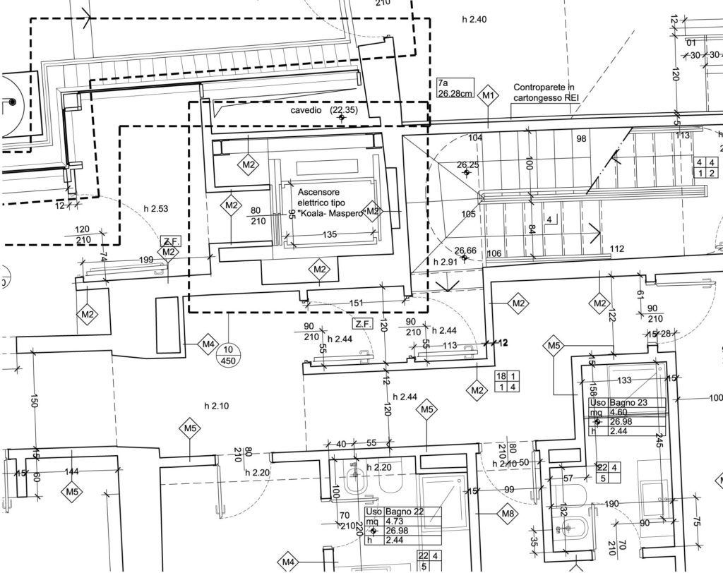
These drawings will be in general developed to a scale normally between 1:200 and 1:50.
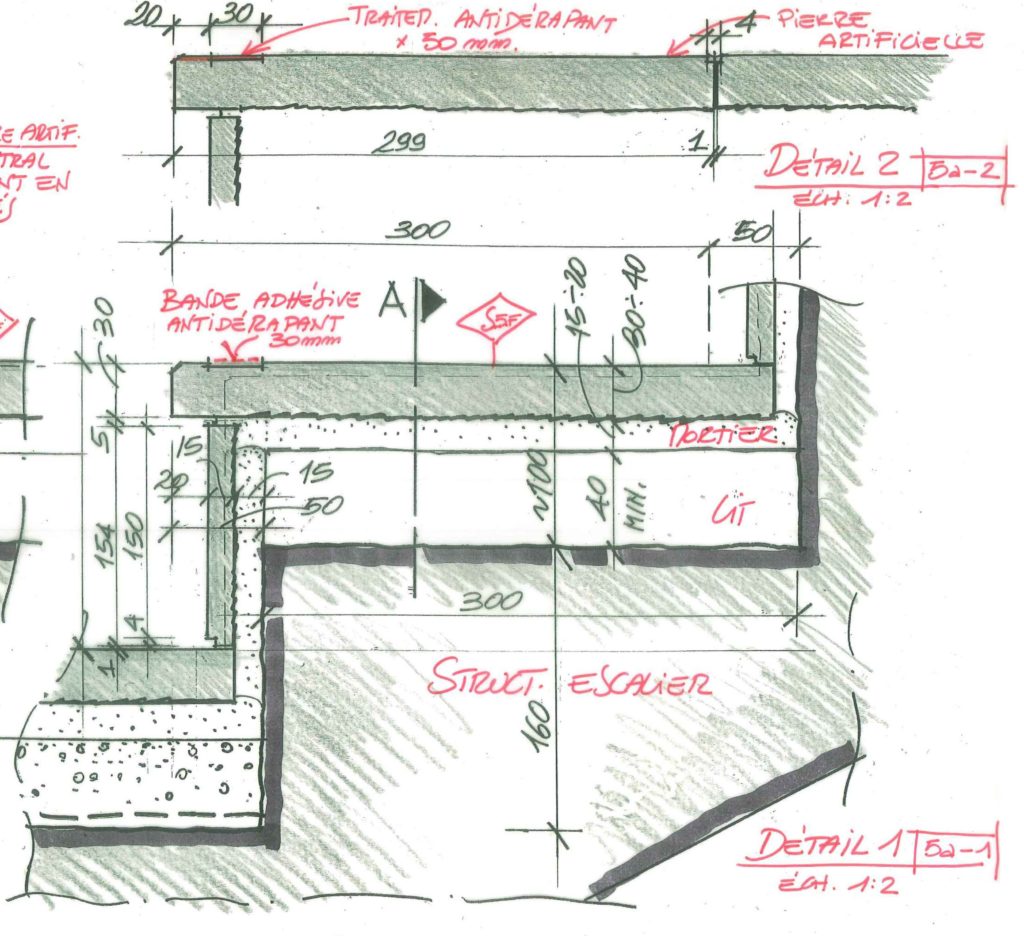
For particularly connoted environments (generally small and detailed environments), we will then move on to larger-scale drawings from 1:50 to 1:10.
More accurate details describing objects, components, and special technical solutions will vary from 1:20 to 1:1.
Finally, schedules and legends will illustrate the repetitive elements of the project, such as:
- Doors, windows, curtain walls;
- Walls and partitions;
- Balustrades and railings;
- Etc.
Construction drawings and BIM
Over the last 30 years the executive design has moved from manual realization to development with CAD programs. BIM is the technology that allows geometric information to be integrated into a 3D model and information about materials, technologies, costs, management and, in general, all building data. With BIM software, the executive design inherits the modeling already carried out in the previous final phase and enriches its contents, to arrive at a “Definition Level”- LOD 300, comparable to the Italian LOD D (UNI standard 11337):
“The elements of the model have a degree of detail that allows the generation of constructive documents and traditional executive drawings. The elements are precisely modeled and defined in terms of quantity, size, shape, and position. In modeling, analysis and simulations are possible on all elements and systems that have been detailed within the 3D model”
The advantage of using BIM to write executive drawings is:
- cataloguing model elements according to a shared structure with accounting documents, special procurement specifications and job planning
- extraction from the data model, schedules, and quantity
- direct interface with other disciplines (Structural and MEP -Mechanical, Electrical Plumbing- models).
The following activities are possible through a series of applications:
- control of interference between different design disciplines (Architectural, Structural, MEP);
- simulation of the construction phases;
- cost planning over time;
- creation of dynamic metric calculation.