Building Information Modeling, (BIM), is a method for optimizing the planning, construction and management of constructions with the help of software, or rather, all relevant data of a construction is collected, combined and digitally connected. Virtual construction is viewable as a three-dimensional geometric model. However, a three-dimensional model of the geometry of a building used only for graphic simulations (rendering) cannot be considered BIM. Building Information Modeling (BIM) is used both in the construction industry for design and construction (architecture, engineering, technical facilities) and facility management.
“Facility management” is defined as everything that relates to the management of buildings together with related plants and services, such as, for example, electrical and plumbing systems, lighting, air conditioning systems, but also cleaning services, company catering, concierge, gardening, corporate fleet, supervision, etc.
Collaboration processes
Modeling using BIM software aims at supporting the communication, cooperation, simulation and optimal improvement of a project along the complete life cycle from planning to construction. The life cycle of the built work is defined in a path that goes from the design phase through the implementation phase to that of use and maintenance.
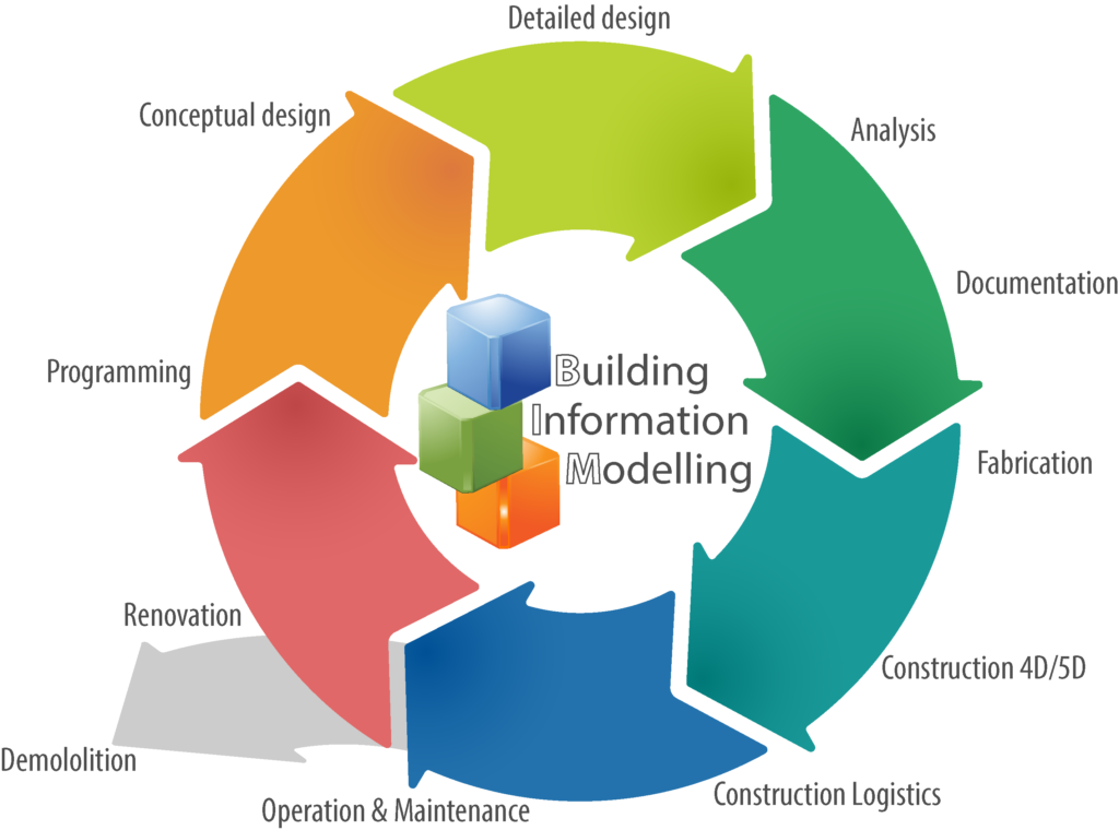
A BIM project, in which many actors (be these Architects, Engineers, Surveyors, Experts, Builders, Customers) meet and collaborate and where a large amount of information is managed, must be regulated because BIM does not mean the mere possession of some information but the activity of sharing this information.
So, it can be said that BIM, used as a name, is the representation of a different data model of a building, related to the different disciplines that define it, a model that can contain any information about the building or its parts. The most commonly collected information in a BIM is geographical location, geometry, material/component/system properties and technical elements, implementation phases, maintenance operations, end-of-cycle disposal. There’s no standard definition of BIM; there’s a high number of definitions used on published works or the internet. However, a European standard for standardizing definitions is being worked on.
Levels of model’s sophistication
Building Information Modeling can be applied with different levels of sophistication (even a simple CAD falls within the information model) that correspond to the different levels of shared collaboration in a construction project.
This parameter is important for establishing BIM capabilities and to make a quick and accurate assessment of an organization’s ability to deliver BIM services. As our level of sophistication increases, collaboration between the various parties increases as well:
Level 0 – Standardized CAD: Requires traditional work to be organized around a standardized system.
Level 1- BIM Lonely or uncooperative: You use the parametric design and data management method within your workflow but do not establish any kind of collaboration with other professionals. The work follows standards, internal or international, especially with regard to the nomenclature of the elements.
Level 2 – BIM Collaborative: effective collaboration between building design stakeholders who all work in BIM. They operate separately on their own model and the collaboration is coordinated by the BIM Leading consultant, which is tasked with bringing the various models together into a single federated model.
Level 3 – Shared BIM: The ultimate goal is for all professionals to work on the same model at the same time and receive updates in real time.
The path to BIM adoption is generally seen as a gradual path to growth, from a process divided into phases to a process in which everyone involved in building the model works in sync, collaborating on the same virtualization of the building. The ultimate goal is seamless full collaboration.
Model size
The concept of dimension in BIM takes on a different meaning than what we are used to: it is not only a purely spatial identification but must be understood as additional information, which goes beyond classic architectural modeling.
UNI11337 rules identify:
3D modeling: related to geometric modeling;
4D modeling: refers to the time or information about the project program;
5D modeling: provides information about cost management;
6D modeling: related to structure management;
7D modeling: for sustainability assessment;
8D modeling: occupational safety and health.
All of these elements can be found within a Level 2 or Level 3 BIM model

Level of Detail (LOD)
There is a specific terminology aiming at precisely defining the level of depth of the information contained within the BIM model. In Italy, UNI113337:2017 defines LODs as “Object Development Level” and is broken down into LOG and LOI.
- LOD: Level of Development. It includes both the graphical representation and the level of information linked to the model (LOD=LOG+LOI).
- LOG: Level of Geometry (also called level of detail). It tells us something about the appearance, the geometry, of the element. LOG can range from a schematic or symbolic representation of a product, to a detailed, manufacturer-specific representation.
- LOI: Level of Information. It stands for the non-geometric, technical information of a model. Content with a high LOI, for example, contains manufacturer-specific information such as price and stock information.
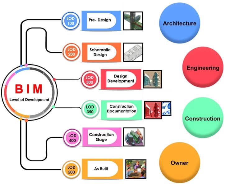
LOD can be understood as a reference to the reliability of a model, for all parties involved in the project. It is the degree to which an element’s geometry and attached (non-graphic) information have been thought through. LODs allow specifying and articulating the construction of a BIM model, with the same degree of definition of the contents and a high degree of clarity, throughout all phases: from conception to construction. Today, 6 levels per degree of development generally apply, according to the American scheme (AIA 208):
LOD 100: Conceptual Design. The element is represented in a generic, schematic, symbolic way. All information is still approximate.
LOD 200: Design Development. The element is displayed inside a generic system with a recognizable shape. For example, a staircase is modeled with simplified steps, but at the footprint level, the total width and length information, start and finish levels, and quote of intermediary landings must be accurate.
LOD 300: Documentation. The quantity, shape, positioning size and orientation of the element are inferred and measurable directly by interrogating the model, without consulting any of the accessory documentation. For example, the stratigraphies are depicted each with their own material and thickness, within a wall system that is not yet divided into parts. The wall types must be clearly encoded. Interferences from inserts such as doors and windows must be modeled.
LOD 350: Model Coordination. In addition to what is specified within 300 LOD, LOD 350 also models the elements that are required for coordination, such as supports and connectors. For example, as far as foundations are concerned, joints and armor are modeled in detail.
LOD 400: Ready for construction. The element is modeled and specified with a level of detail that allows it to be manufactured.
LOD 500: Field verified. This level means that the elements in the model have been verified in the field, checked in the actual building after completion. As-built models fit in this category. This does not mean that the systems have been modeled at a higher level of information or with more detail. At LOD 500, a model can look the same as a model at LOD 400. The difference is that at LOD 500, the model has been verified on site – and therefore has a higher level of reliability
The overall scale of the Italian UNI standard 11337:2017 is:
- LOD A: symbolic object;
- LOD B: generic object;
- LOD C: defined object;
- LOD D: detailed object;
- LOD E: specific object;
- LOD F: executed object;
- LOD G: updated object.

BEP – BIM Execution Plan
Once it has been clarified what type of information is required by the client, it is time to plan activities through the use of BEP, a specific document that service providers must prepare to explain how the modeling and information aspects will be implemented during the development of a BIM project. The main purpose of the BEP is to ensure that all stakeholders within the project are aware of the risks and opportunities associated with the adoption of BIM in project workflows. For this step, it is recommended that the BEP be developed in two phases, i.e. pre- and post-assignment of the contract. The purpose of the pre-contract BIM Executive Plan (BEP) is to demonstrate that the approach proposed by the main supplier (leader) is supported by partners (sub-suppliers) with the skills, experience and expertise needed to meet the Employer’s Information Requirements (EIR). In this sense, we could say that the pre-contract BEP obliges the row leader to pre-select the most appropriate partners to carry out BIM activities correctly.
In some contracts in Italy, the EIR (Employer’s Information Requirements), containing requests from the Client, is called “Capitolato Informativo”. After the tender, the BEP must be re-presented by the supplier to the employer to confirm the capabilities and confirm that all stakeholders have agreed and are committed to comply with the BEP. The post-contract BEP must be submitted by the main supplier to the customer on behalf of the entire supply chain and must include a summary of their capabilities and responsibilities. Sub-suppliers will be responsible for the entire flow of information in their supply chain. With the Building Execution Plan, you can ascertain the project team’s expertise, assist the client in assessing feasibility, know the team’s responsibilities, add the advice of a BIM Project Manager as an additional figure, and, more generally, promote a better workflow.
Data Sharing Environment – CDE or ACDAT
It is defined within the BEP and is the virtual space for collecting, managing, and sharing all the information in the entire BIM stream. The different actors involved in the construction can tap into the data and store their own. The environment is divided into 4 sections, each related to a progressive phase of information sharing:
- L0 – Work in Progress Phase – Revision
- L1 – Sharing Phase
- L2 – Published Documentation Phase
- L3 – Archive Phase (L3 Valid and L3 Passed)
In phase L0 – Work in progress. Each team deposits the models and information being processed without the ability to share them with other teams, until the time of validation by the Team Manager.
In phase L1 – Sharing Phase (Shared). Models of different disciplines are pooled to enable coordination and exchange of information with the other working groups. Once the different models have been validated and approved by the client, the information can be passed into the third area.
Phase L2 – Published Documentation. Everything that was previously defined is shared.
Phase L3 – Archive. All the documents, templates, and drawings that are provided by the BIM process are saved and cataloged.
Therefore, if the BIM model concerns programming and design where traditional preliminary, final, and executive design definitions are condensed, the next steps are production (PIM) and exercise (AIM) such as management, maintenance, and repair.
PIM – Project Information Model
It is the model inside Archive from which to define the Project Information Model for the construction phase (testing/delivery), created thanks to the information delivered by all project participants and which will then be constantly updated.
PIM consists of design virtualization in order to carry out engineering surveys and analyses aimed at improving and optimizing the structure of the building. In practice, its aim is to ensure that the different parts of the project match and reflect the design objectives.
AIM – Asset Information Mode
It is the basis for management and maintenance operations. This structure represents a Construction Asset Live-Cycle that necessarily triggers an interdisciplinary coordination mode and activity, completely new for many technicians. The existing heritage project also focuses particularly on the interest of the aim intervention and implies that BIM is also related to aspects of pre-assessment (diagnostics, historical-material compatibility, etc.).
Conclusions
A detailed and accurate model of the artifact represents an opportunity for all stakeholders in the project, allowing to optimize and speed up the planning and implementation processes of the intervention resulting in significant savings of time and money and reduction of any issues in the executive phase.
Finally, the BIM Decree (DM 560 of 1 December 2017) has established the modalities and times of progressive introduction by the contracting stations of the mandatory use of specific electronic methods and tools, such as modeling for construction and infrastructure, in the design, construction and management phases of the works and related checks.
The obligation to use electronic modeling methods and tools begins:
- from 2019 for works amounting to 100 million euros;
- from 2020 for complex works over 50 million euros;
- from 2021 for complex works over 15 million euros;
- from 2022 for works over 5.2 million euros;
- from 2023 for works over 1 million euros;
- from 2025 for all new works.